01-08-2025


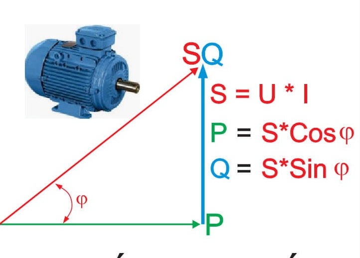
The power factor is determined by the cosine of the phase angle between voltage and current. In AC circuits, the phase angle between voltage and current is aligned, or in other words, zero. But, practically there exists some phase difference between voltage and current. The value of the power factor always lies between 0 and 1. For a purely capacitive circuit, it is 0 and for the purely resistive circuit, it is 1.
In an alternating current (AC) system, the power factor (PF) is defined as the ratio of active power (P, expressed in kW) to apparent power (S, expressed in kVA):

where φ is the phase angle between the fundamental components of voltage and current, in accordance with IEC terminology.
According to IEC definitions:
Transformers, generators, and switchgear are therefore rated in VA or kVA, as their thermal and electrical stresses depend on the total current corresponding to apparent power, not solely on active power.

In a purely resistive circuit, voltage and current are in phase (φ = 0).
The instantaneous power remains positive over the entire cycle, indicating that energy flows unidirectionally from the source to the load and is fully utilized as active power.
Under this condition: P = S and PF = 1
In inductive loads, such as motors and transformers, current lags voltage (φ > 0).
During certain portions of the AC cycle, the instantaneous power becomes negative, indicating that energy is returned from the load to the source.
This bidirectional energy exchange is the physical origin of reactive power. Reactive power does not represent energy loss but is necessary for establishing magnetic fields in inductive equipment.
Reactive power is an inherent operational requirement of inductive loads. Electric machines cannot operate without magnetic flux, and magnetic flux cannot be established without reactive power.
Therefore, reactive power is not detrimental in itself; however, excessive reactive power increases current flow, resulting in:

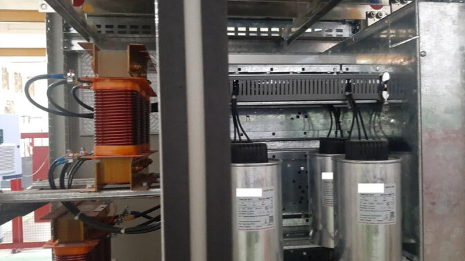
To reduce reactive power demand from the supply network, power factor correction is commonly achieved by connecting capacitors in parallel with inductive loads. Capacitors provide leading reactive power, partially or fully compensating the lagging reactive power of inductive loads.
Improving the power factor enhances the efficiency of electricity generation, transmission, and distribution systems and aligns with IEC-recommended practices for power quality management.