24-12-2025

The growing use of power electronic devices amplifies the harmonic distortion in electrical systems.
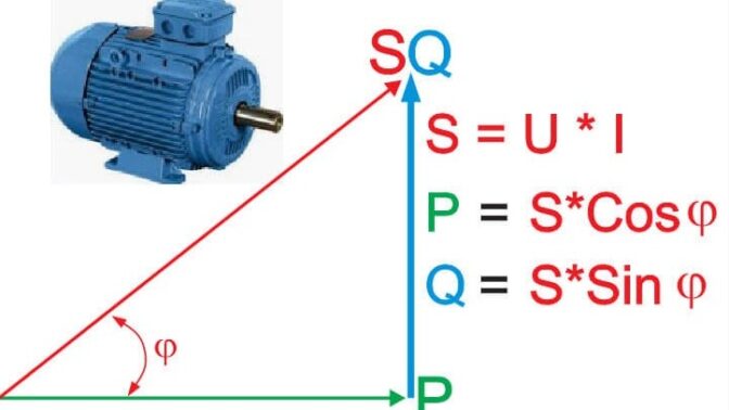
One of the unwanted effects is the overheating of capacitor banks that are needed to maintain the power factor within the parameters required by the power authority, with a resulting, significant reduction in the average working life.
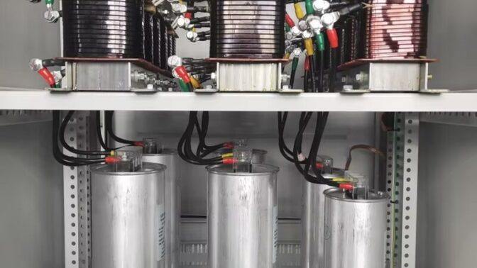
The ideal solution is to insert block reactors in series with capacitor banks. The power factor correction system devised thus, as well as continuing to perform the function of correcting the power factor, anticipates the amplification of the harmonic distortions caused by the resonance between the capacitor’s capacity and harmonic distortion due to power electronic devices.
The coupling of capacitors and reactors is a delicate procedure. BTB Electric combines experience in designing power factor correction systems with that of magnetic parts. In the design phase, all the aspects involved are taken into consideration:
Increase in the voltage at capacitor terminals due to the Ferranti Effect.
Allowable harmonic overload in the capacitors according to the current legislation.
Reactive power actually delivered.
The parameters to consider in relation to a correct coupling include:
The RSS current [Irms]: the square root of the sum of the squares of the rated current at industrial frequency and all current values at the frequencies specified in the rated current spectrum.